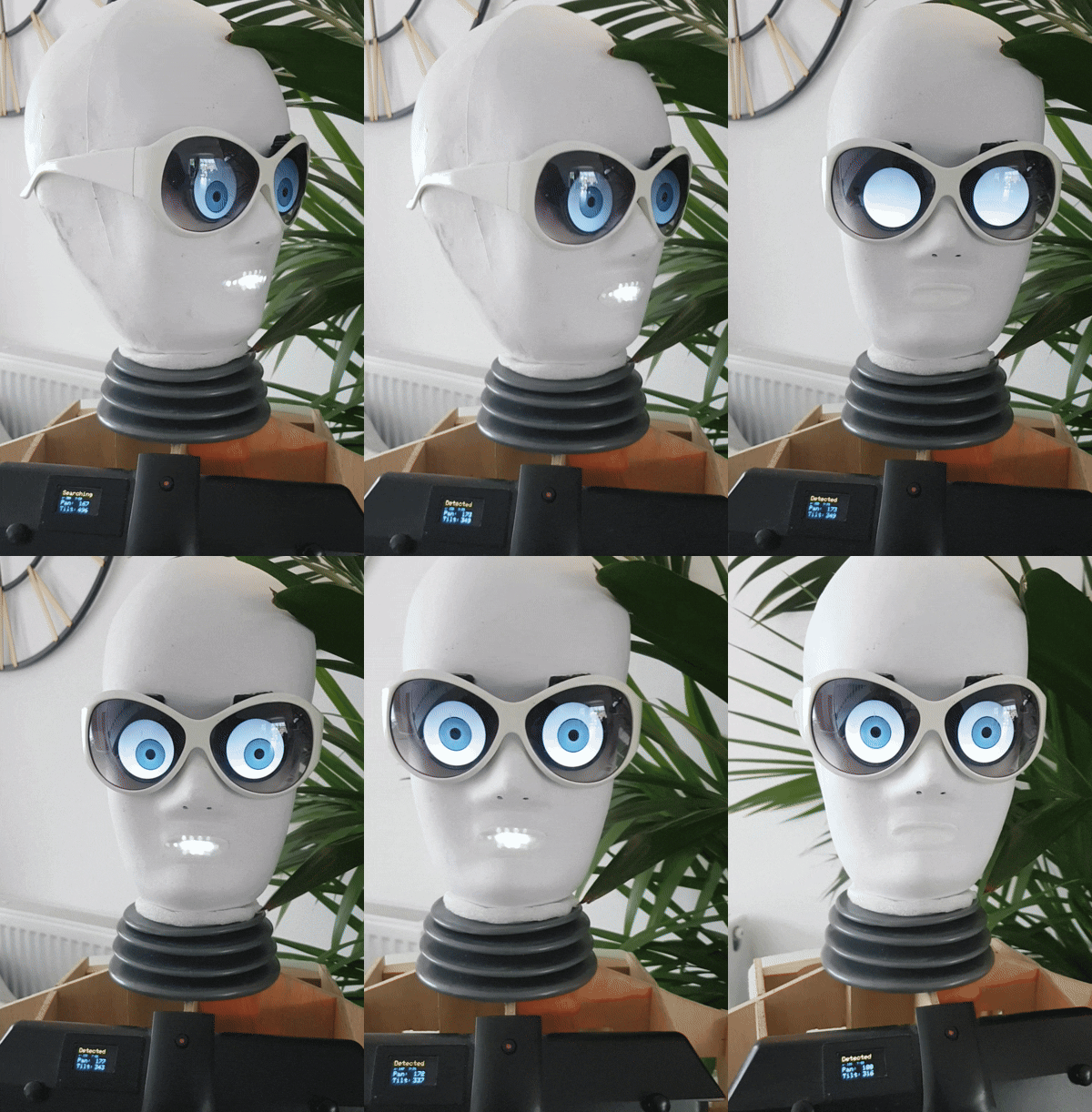
FaceTracker is an autonomous Edge Computing solution for real-time computer vision. By integrating an ESP32-CAM with a PCA9685 PWM controller, the system performs onboard facial centroid tracking—translating visual coordinates directly into physical motion without the need for external processing or Wi-Fi.
|
|
|
Most ESP32-CAM implementations are limited to "CameraWebServer" streams. This project moves the intelligence to the Edge, allowing the microcontroller to scan, detect, and act autonomously. By eliminating the latency of a web browser middleman, the system calculates positional error vectors in real-time. The result is a self-contained robotic sensor that centers on human subjects using high-speed I2C communication, making it ideal for mobile robotics and interactive animatronics. |
|
- Autonomous Centroid Tracking: Onboard processing calculates the X/Y displacement required to maintain target alignment at the frame center.
- Low-Latency Edge AI: Uses the MTMN (Multi-Task Cascaded Convolutional Networks) model for face detection without cloud or app dependency.
- Hardware-Accelerated PWM: Offloads servo pulses to a PCA9685 via 400kHz Fast-Mode I2C, ensuring 12-bit resolution and jitter-free movement.
- Real-Time Telemetry: Local SSD1306 OLED integration provides instant feedback on coordinate mapping and system health.
- Optimized Bus Architecture: Maximizes the ESP32-CAM's limited GPIO by daisy-chaining all peripherals on a single I2C bus.
- ESP32-CAM (AI-Thinker):
- Dual-core LX6 CPU @ 240MHz.
- Integrated OV2640 image sensor.
- PCA9685 16-Channel PWM Driver:
- 12-bit resolution for precise angular servo increments.
- Addresses I2C bus bottlenecking by managing pulse timing independently.
- Actuators: Dual SG90/MG90S Micro Servos for Pan and Tilt.
- Display: SSD1306 OLED for coordinate debugging.
All external peripherals are synchronized via the I2C Serial Bus to conserve GPIO pins for the camera interface.
| Peripheral | ESP32-CAM Pin | Function | Protocol |
|---|---|---|---|
| PCA9685 | GPIO 14 | SDA | I2C Data |
| PCA9685 | GPIO 15 | SCL | I2C Clock |
| SSD1306 OLED | GPIO 14 | SDA | Shared Bus |
| SSD1306 OLED | GPIO 15 | SCL | Shared Bus |
| Logic Power | 5V / GND | VCC / GND | Logic Supply |
Important
Servo Power: Always use a dedicated 5V power supply for the PCA9685/Servos. Drawing servo current through the ESP32-CAM will cause brownouts and core resets.
The system identifies facial landmarks and determines the Error Vector relative to the QVGA resolution center (
- The Goal: Minimize the delta between the detected face centroid and the frame origin.
- The Action: The ESP32 calculates a proportional correction and updates the PCA9685 registers to adjust the servo duty cycle.
- Acquisition: Frame capture via OV2640 DMA.
- Inference: MTMN model detects faces and produces bounding box coordinates.
-
Control: Software calculates
$X, Y$ offsets and generates I2C commands. - Feedback: Coordinates are pushed to the OLED and Serial Monitor.
- Actuation: Servos pivot to center the target within the frame.
- Hardware: Assemble the circuit using the shared I2C pinout.
- Project Initialization:
- Create a new project in PlatformIO.
- Select AI Thinker ESP32-CAM as the board.
- Critical Configuration Steps: This project uses a legacy framework (Espressif v1.0.4) that requires manual file handling to resolve missing
fd_forward.handADS1115-Drivererrors. Complete these three steps before attempting to compile:- 1. Replace
platformio.ini: Overwrite the default file in your project root with the specific configuration provided (ensuring it usesplatform = espressif32@1.12.4). - 2. Replace
main.cpp: Copy your code into thesrcfolder, replacing the existing boilerplate file. - 3. Manual Library Install: Copy the
ADS1115_Driver-1.0.2andesp32camfolders into the project’slibfolder. This allows the missing legacy files to be available for the compiler.
- 1. Replace
- Calibration: Define
SERVO_MINandSERVO_MAXwithin the code for physical calibration. - Build & Upload: Connect your ESP32-CAM via an FTDI adapter and click Upload in PlatformIO.
To ensure the compiler sees your files, your project directory should look like this:
Your_Project_Folder/
├── lib/
│   ├── ADS1115_Driver-1.0.2/
│   └── esp32cam/            <-- Contains legacy fd_forward.h
├── src/
│   └── main.cpp             <-- Your actual code
└── platformio.ini           <-- The specific v1.12.4 config
- I2C Communication: If the OLED or PCA9685 is not detected, verify that GPIO 14/15 are not being pulled high/low by other peripherals.
- FPS Drop: Ensure "Core Debug Level" is set to "None" in the IDE to maximize CPU cycles for detection logic.
- Servo Jitter: Confirm the ground (GND) is common between the ESP32-CAM and the external servo power supply.
- ESP32-S3 Port: Leveraging vector instructions for higher frame rates.
- PID Implementation: Replacing simple proportional tracking with a full Proportional-Integral-Derivative loop for fluid motion.
- Distance Logic: Using bounding box area to estimate target distance and adjust tracking speed dynamically.
© 2026 MatsRobot | Licensed under the MIT License